Inhaltsverzeichnis
ESP8266
Sehr geil: 1D-Games auf einem einzelnen Neopixel-String. Zahlreiche Spiele, leicht zu bauen: https://kobebeefg.gumroad.com/l/1Dgame
Einführung:
https://tttapa.github.io/ESP8266/Chap01%20-%20ESP8266.html
ESP8266 und ESP8285 Module Anleitung:
Sehr gut, besonders welche Boards es gibt etc. http://stefanfrings.de/esp8266/
https://www.exploreembedded.com/wiki/Arduino_Support_for_ESP8266_with_simple_test_code
Flash new Firmware
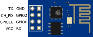
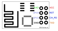
TX(D)/RX(D) müssen bei den Stiften (Anschluss USB/seriellen-Adapter) vertauscht sein.
Beim Einstecken (booten) muss GPIO0 und Ground verbunden sein (kurz oder lang), damit der ESP in den Flashmodus geht.
Tasmota download: Arduino support for ESP8266
Linux
Esptools Python
git clone https://github.com/themadinventor/esptool.git
Erzeugt Verzeichnis esptools
sudo python esptool.py --port /dev/ttyUSB0 write_flash 0x00000 ../Downloads/tasmota-wifiman.bin
Sollte man den Flash mal ganz löschen müssen (z.B. weil der Config verkackt ist):
sudo python esptool.py --port /dev/ttyUSB0 erase_flash
ESPtool
Ist bei Ubuntu schon dabei.
Checken, was für Flash-Speicher verbaut ist (Größe) (ist ja extern beim ESP)
esptool --port /dev/ttyUSB0 flash_id
flashen
If you have an ESP-01 or other device without built-in USB, you will need to enable flashing yourself by pulling GPIO0 low or pressing a „flash“ switch, while powering up or resetting the module.
sudo esptool --port /dev/ttyUSB0 write_flash -fm dio 0x00000 tasmota.bin
CH340 Serial USB-driver
Manche ESP haben einen USB-Chip eingebaut (z.B. Dmos D1 mini), der den CH340 driver benötigt. Der eingebaute von Ubuntu ist Scheisse (auch 2022 noch). Daher gibt es einen gepatchten driver:
https://github.com/juliagoda/CH341SER
Quelle1)
- cd into the directory where the files are saved
- make clean
- make
- sudo make load
- sudo rmmod ch341 to uninstall the broken driver
- lsmod | grep ch34 to list what modules are currently installed
- Plug and unplug your CH340 device again on the USB port
- dmesg
Expected output (should show „ch34x“ now):
[  xxx] ch34x ttyUSB0: ch34x converter now disconnected from ttyUSB0
[  xxx] ch34x 3-2:1.0: device disconnected
Depending on your root permissions, you may need to configure the serial port with the following two commands. Make sure to adjust the $username with respect to the user ID that is currently logged in.
sudo usermod -a -G dialout $username
sudo chmod a+rw /dev/ttyUSB0
Siehe auch Arduino IDE auf Quellenseite!
Development /Programmierung
DerESP8266 hat 2 UART eingebaut UART0 ist der ganz normale Serielle Anschluss über TX (GPIO1) & RX (GPIO3)
Der ESP8266 verfügt über zwei UART-Schnittstellen: UART0 und UART1. Diese können für die Kommunikation mit seriellen Geräten genutzt werden, haben jedoch unterschiedliche Einschränkungen.
UART0 (Haupt-UART)
Standard-Pins:
- TX: GPIO1
- RX: GPIO3
Eigenschaften:
Volle Duplex-Kommunikation (kann senden und empfangen). Wird standardmäßig für die serielle Kommunikation und Debugging genutzt.
Kann über Software auf andere GPIOs gemappt werden (via Serial.swap()):
- TX: GPIO15
- RX: GPIO13
UART1
Standard-Pin:
- TX: GPIO2
Einschränkungen:
- Nur TX ist verfügbar; RX ist nicht nutzbar.
- Typischerweise für Debug-Ausgaben genutzt.
- Kann nicht für vollständige UART-Kommunikation verwendet werden (kein Empfang).
Arduino IDE
ESP-IDF
IoT Development Framework von Expressif selbst
ESP8266 Projekte
Baudrate
Ich habe den ESP direkt an einen USB-seriellen Konverter an den PC angeschlossen (/dev/USO0). ACHTUNG!!!: Unbedingt 3,3 Volt, keine 5V, sonst Schrott. Kein Problem. Allerdings muss der Chip-Enabled-Pin auf VCC angesclossen sein, sonst geht der ESP nicht. Dann kann man mit der Arduino-IDE mit dem Chip kommunizieren, 115200 Baud. Ich will die Original Firmware behalten, weil ich den ESP eh an einen Arduino Nano anschlisse und ihn nur fürs WLAN brauche. Ich mache das, um zu sehen, ob es funktioniert und um die Baudrate permanent auf 9600 Baud zu stellen. Keine Ahnung, ob das wirklich nötig ist, aber die Kommunikation zum Arduino ist sicher stabiler.
AT+UART_DEF=9600,8,1,0,0
Welche Firmware-Version ist drauf?
ESP8266 and the AT firmware are products of Espressif. They have everything documented on the web site.
The AT command for version is 'AT+GMR'. Bei mir:
AT+GMR

AT version:1.3.0.0(Jul 14 2016 18:54:01)
SDK version:2.0.0(5a875ba)
Farylink Technology Co., Ltd. v1.0.0.2
May 11 2017 22:23:58
OK
AT-Befehle für ESP: http://stefanfrings.de/esp8266/
Mit WLAN verbinden: AT+CWJAP=„Pipping_UG2“,„supergeheim“ das Modul verbindet sich mit dem WLAN Netz „Muschikatze“ und dem angegebenen WPA/WPA2 Passwort. Diese Einstellung wird automatisch dauerhaft gespeichert und beim nächsten Neustart aktiv.
AT+CWJAP?
zeigt an, mit welchem Access Point das Modul gerade verbunden ist. Zum Beispiel:
+CWJAP:„Pipping_UG2“,„5c:49:79:2d:5b:cd“,7,-60 OK
AT+CIFSR
zeigt die IP-Adresse und MAC Adresse des Moduls an zum Beispiel:
+CIFSR:STAIP,„192.168.0.111“ +CIFSR:STAMAC,„5c:cf:7f:8b:a9:f1“ OK
Doorlock \ Türschloss
McLighting v2 - The ESP8266 based multi-client lighting gadget
Open Source projekt zur LED-Steuerung mit ESP
McLighting (the multi-client lighting gadget) is a very cheap internet-controllable lighting solution based on the famous ESP8266 microcontroller and WS2811/2812 led strips. It features among other things a web-interface, a REST-API and a websocket connector.
Because of it's open architecture and APIs it's easy to build new clients for different platforms (iOS, Android, Windows Universal Apps, Siri/Cortana integration, …).
Tuya Infrarot Sender
Billig-China Infrarot-Hub auf ESP-Basis
DeAuther
Relais Boards
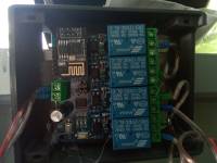
LC Technology 4CH Relay
TASMOTA
Tasmota→Einstellungen→Sonstige Einstellungen→Vorlage
Ist-Zustand (Relais schalten nicht, obwohl Oberfläche so tut, als wäre dem so)
{"NAME":"LC Technology 4CH Relay","GPIO":[224,0,225,0,226,227,0,0,0,0,0,0,0,0],"FLAG":0,"BASE":18}
Tasmota 12.0.2 von Theo Arends
{"NAME":"LC Technology 4CH Relay","GPIO":[52,255,17,255,255,255,255,255,21,22,23,24,255],"FLAG":0,"BASE":18}
2023: bekomm's nicht wieder hin. Vielleicht hier? : https://templates.blakadder.com/LC-ESP01-4R-5V.html
Spezifikationen:
Boardgröße: 60 * 63mm
Schnittstelle an Bord:
- IN +, IN-: 5V Spannungseingang;
- 5V, GND, TX, RX: serielle UART-Port-PIN;
- SWIM, PIN8, NRST: reservierter MCU-Download-Port.
- Taste S1: Änderungsmodus, Standardmodus ist Modus 1
- Taste S2: Zurücksetzen
- LED D1 / D2 / D3 / D4 (rot): Relais arbeitet LED, LED leuchtet bei eingeschaltetem Relais
- LED D7 (rot): Anzeige für Modus 1
- LED D5 (blau): Anzeige für Modus 2
- LED D6 (grün): Werkstattindikator, genaue Details wie folgt:
- Wenn er gelöscht wird, wird er vom Router konfiguriert oder getrennt.
- 0.5s schnelles Blinken stellt dar, dass Handy-APP WIFI-Konto und Kennwort für ESP-01-Modul konfiguriert
- 2S blinkt langsam, um die Konfiguration zu beenden, und warten auf die Verbindung mit dem Mobiltelefon über TCP
- LED leuchtet immer auf TCP-Verbindungen mit Mobiltelefon erfolgreich
Anschluss für reservierten Zwei-Kappen-Jumper:
- Im Allgemeinen, fügen Sie sie nach unten, das ist RX zu RX1, TX zu TX1. Setzen Sie sie nach oben, wenn Sie es als USB-Modul verwenden
- COM1 COM2 COM3 COM4: Gemeinsames Terminal;
- NC1 NC2 NC3 NC4: normal geschlossen
- NO1 NO2 NO3 NO4: normal geöffnet
Steuerbefehl für Relais (Hex-Format):
- Relais 1 öffnen: A0 01 01 A2
- Relais 1 schließen: A0 01 00 A1
- Relais 2 öffnen: A0 02 01 A3
- Relais 2 schließen: A0 02 00 A2
- Relais 3 öffnen: A0 03 01 A4
- Relais 3 schließen: A0 03 00 A3
- Relais 4 öffnen: A0 04 01 A5
- Relais 4 schließen: A0 04 00 A4
Anleitung sieht auch gut aus: https://gripseljagd.wordpress.com/2022/02/08/tasmota-relais-das-3te/
2er Relais Board (Garage)
2 Relais
ESP-12F 5V/8-80V 2 Channel Relay Board (ESP12F_Relay_X2) 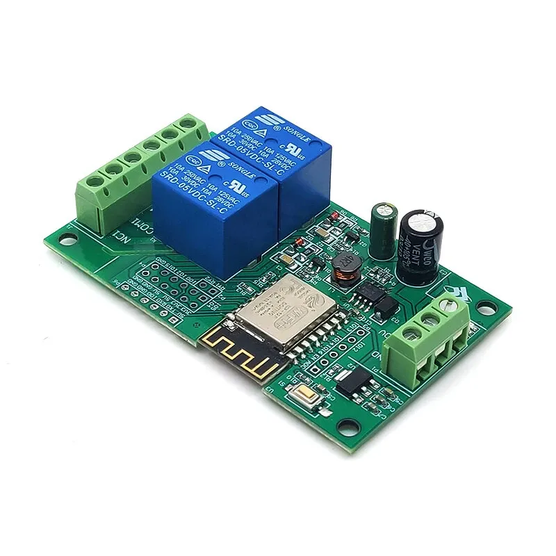
5x8cm
zusätzliche Kontakte (gegen GRN, Pull-Up 10k Ohm) 2)
Stecker:
- GPIO 12
- GPIO 13
- GPIO 02
- Schwarz = GND
- Switch1 (Garagentor offen): GPIO 02
- Switch2 (Garagentür): GPIO 12
- Switch3 (Garagentür geschlossen): GPIO 13
Ein Relais nur kurz schalten: https://nerdiy.de/de_de/tasmota-nachlaufen-eines-relais-einstellen/
SetOption26 (Anzeige der Relais-Indizes) aktivieren:
SetOption26 1
Weitere Beispiele für den Bereich 0,1 bis 11,1:
Haltezeit von 3,7 Sekunden:
PulseTime 37
Haltezeit von 4,2 Sekunden:
PulseTime 42
PulseTime deaktiveren:
PulseTime 0
ESP32
Kamera
Blog-Eintrag flashen, Arduino fui, Probleme: https://www.fambach.net/esp32-cam-modul/
esp32-cam
Tasmota ESP32 Cam
https://github.com/prusa3d/Prusa-Firmware-ESP32-Cam
Turn on/off rtsp: https://cgomesu.com/blog/Esp32cam-tasmota-webcam-server/#rtsp-server
Konsole: command:
WcRtsp 1
Now, the video stream should be accessible via RTSP using the following address:
rtsp://DEVICE_IP:8554/mjpeg/1
Vogelcam1: .137
Vogelcam2: .60
Um den RTSP-Stream zu youtube zu übertragen, braucht man einen Zwischenserver Ein Raspi sollte reichen. Lt. ChatGPT reicht evtl. ein 2 oder 3: Umkodieren von RTSP zu H264. YouTube erwartet einen RTMP-Stream mit einem effizienteren Video-Codec wie H.264.
ffmpeg -rtsp_transport tcp -i rtsp://<KAMERA_IP>:8554/mjpeg/1 \
-f lavfi -i anullsrc \
-c:v libx264 -preset veryfast -tune zerolatency \
-c:a aac -ar 44100 -ac 2 \
-f flv rtmp://a.rtmp.youtube.com/live2/<DEIN_STREAMSCHLÜSSEL>
- -f lavfi -i anullsrc : Erzeugt einen stillen Audio-Stream, da YouTube einen Audio-Kanal erwartet.
- -rtsp_transport tcp : Verwendet TCP für den RTSP-Transport, was stabiler ist.
- -i rtsp:<KAMERA_IP>:8554/mjpeg/1 : RTSP-URL deiner Tasmota-CAM. * -c:v copy : Kopiert den Video-Stream ohne Neukodierung. * -c:a aac : Kodiert den Audio-Stream im AAC-Format. * -f flv : Setzt das Ausgabeformat auf FLV, das von YouTube erwartet wird. * rtmp:a.rtmp.youtube.com/live2/<DEIN_STREAMSCHLÜSSEL> : Ziel-URL für den YouTube-Live-Stream.
Tasmota-Cam-releases
External/internal WiFi antenna
Quelle3)
The standard ESP32-CAM board utilizes an internal antenna on the PCB. However, this antenna can sometimes cause issues with the quality of the WiFi signal, leading to slow photo uploads to PrusaConnect or connectivity problems. Fortunately, there is an option to connect an external antenna. This requires changing the resistor position, as shown in the picture below. Then, you can use a 2.4GHz Wi-Fi cable with a U.FL to RP-SMA connector and a standard 2.4GHz WiFi antenna
Infrarotfilter entfernen
https://www.visualmicro.com/page/ESP32-NightVision.aspx
Der Filter ist ein quadratisches, bunt glänzendes Glas auf der Oberseite. Man muss vorne die linse mit einem Skalpell rundrum aufschneiden.
IR-Scheinwerfer
IR-Licht:
-ich denke, der kleine Poi regelt, ab wie viel Licht (Sensor) sich das IR-LED einschaltet.
alt:
Expressif-Entwicklungsumgebung installieren
Firmware ESP32 für OV2640 Kamera-Modul: https://github.com/bkeevil/esp32-cam
Meine Kamera ist eine M5Stack ESP32CAM mit OV2640, aber das Standard-Template von make menuconfig funktionierte nicht (Kamera hat KEIN PSRAM) Kameras ohne externes PSRAM können nur 800×600 Pixel anzeigen/streamen, weil der Speicher fehlt (egal, was die Kamera kann)!
Hier habe ich das PIN-Layout dieser Kamera gefunden: https://randomnerdtutorials.com/esp32-cam-camera-pin-gpios/#board5
make menuconfig
Important settings are:
- Select a USB port for uploading the firmware under Serial Flasher Config → Default serial port
- Ensure that Partition Table → Parititon Table is set to use the *Custom partition table CSV) called „partitions.csv“
- Select what board you are using under Camera Web Server → Camera Pins (SIEHT LAYOUT!)
- If your board has an LED flash, enable it under Camera Web Server → LED Illuminator (NEIN!)
- You can select default wifi settings under Camera Web Server → Wifi Settings
- If your board has an SSD1306 based OLED display, enable it under Component Config → SSD1306 Configuration and select pins for SDA and SCL (NEIN!)
- To use additional external SPI RAM that may be on your board, enable it using Component Config → ESP32 Specific → Support for external, SPI-connected RAM (NEIN!)
- To enable font overlays, under Font Configuration check Store Font Partition (Uses approximately 240K of flash)
- Under Component Config → Camera Configuration select camera type OV2640 and pin it to Core1 (Ja!) (Schalte 'Use Hardware I2C1 for SCCB' ein!)
- Under Component Config → WiFi pin the WiFi task to Core0 (Ja!)
- Enable NTP and select a default NTP server and timezone under NTP configuration
Wenn alles schon installiert ist und man weiteren ESP flashen will:
cd ~/esp/esp-idf/ // Um dieses Skript aufzurufen:
. ./export.sh  // Die Pfade setzen...
cd ~/esp/myprojects/esp32-cam/ // Da ist mein Projekt
make menuconfig // Einstellungen vornehmen
make app // Compilieren
make flash // Auf ESP schreiben
make monitor // Schauen, was ESP macht...
Web Camera URLS
Picture: http://IP/capture
Stream: http://IP:81/stream
Control LED: http://IP/control?var=led_intensity&val=[0...255]
Pin assignment for the M5-stack ESP32 camera without PSRAM.

#define PWDN_GPIO_NUM     -1
#define RESET_GPIO_NUM    15
#define XCLK_GPIO_NUM     27
#define SIOD_GPIO_NUM     25
#define SIOC_GPIO_NUM     23
#define Y9_GPIO_NUM       19
#define Y8_GPIO_NUM       36
#define Y7_GPIO_NUM       18
#define Y6_GPIO_NUM       39
#define Y5_GPIO_NUM        5
#define Y4_GPIO_NUM       34
#define Y3_GPIO_NUM       35
#define Y2_GPIO_NUM       17
#define VSYNC_GPIO_NUM    22
#define HREF_GPIO_NUM     26
#define PCLK_GPIO_NUM     21
Derzeit bekomme ich nur ein 800×600-Bild raus, wenn ichs auf 1200 stelle…
Meine sdkconfig ESP32 Cam M5Stack M5Cam ohne PSRAM: skdconfig.txt
Ein Bild mit Micro Python aufnehmen: https://lemariva.com/blog/2019/09/micropython-how-about-taking-photo-esp32
Allgemein
ESP32 Cam: https://www.fambach.net/esp32-cam-modul/
https://www.instructables.com/id/ESP-32-Camera-Streaming-Video-Over-WiFi-Getting-St/
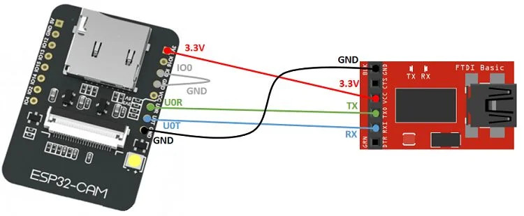
Achtung: In dem Bild ist IO0 mit dem GND verbunden. Das muss man so machen (mit *allen* ESP), um den ESP in dem Schreibmodus zu bekommen. Man kann diesen PIN natürlich auch anders an GND bekommen. Zum Testen nach dem Schreiben einfach den IO0 lösen und er verhält sich ganz 'normal' (und bekommt seinen Strom von USB-TTL-Konverter via USB-Buchse).
https://www.elementzonline.com/blog/Accessing-ESP32-CAM-Video-Streaming-from-anywhere-in-the-world
Streifen im Kamera Bild
Lars (Siehe Kommentare unten) hat ein paar Versuche gemacht. Es hat sich als vorteilhaft herausgestellt das Modul am 5V Anschluss zu betreiben. Quelle4)
Kamera-Einstellungen fernsteuern: 5)
Stream speichern unter Linux: https://www.fambach.net/mpv-linux/
Wasseruhr /Stromzähler auslesen mit ESP32Cam
Mit AI
https://community.symcon.de/t/wasseruhr-auslesen-mit-einem-esp32-cam/122960
AI-on-the-edge-device: https://github.com/jomjol/AI-on-the-edge-device/wiki/Installation
WLAN-Modul des ESP via Arduino nutzen
Das macht eigentlich keinen Sinn, weil der Arduino (nano) seeehr viel leistungsschwächer ist als ein ESP8266. er ESP wird zudem von der Arduino-Entwicklungsumgebung unterstützt. Aber ich konnte ihn trotzdem nicht programmieren, weil ich den USB-Treiber unter Linux nicht installiert bekommen habe und ihn nicht ansprechen konnte.
Daher habe ich dieses Knowhow aufgebaut.
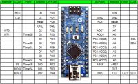
Arduino Nano v3.0 with ESP8266: https://arduino.stackexchange.com/questions/17590/arduino-nano-v3-0-with-esp8266

